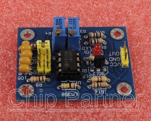
Description
Module Scope:
1. Used as a square wave signal generator produces a square wave
signal for the experimental development use.
2. Used to generate the square wave signal to drive a stepper motor
drive.
3. Produce adjustable pulse for the MCU to use.
4. Generating adjustable pulse to control the associated
circuits.
A brief description:
1. Size: 3.5CM * 4.6CM
2. The main chip: LM358;
3. Input voltage: 5V-12VDC.
4. Input Current: ? 100MA;
5. Output amplitude: close to the input voltage;
6. Frequency adjustment range: 0.07HZ-2KHZ (also cycle in about
0.45 milliseconds to 15 seconds);
Frequency adjustment methods:
The board has four the shorting cap can select the frequency:
Plug 0 short-circuit the cap, that is, all four short circuit cap
removed files for high-frequency, the longest cycle upwards to 0.3
seconds;
Inserted a short circuit cap, the longest cycle can be adjusted to
about 4 seconds;
Inserted two short-circuit cap, the longest cycle can be adjusted
to about 7 seconds;
Inserted three short cap, the longest cycle can be adjusted to
about 10 seconds;
Inserted four short circuit cap, the longest cycle can be adjusted
to about 15 seconds;
7. Duty cycle adjustment range: 0% to 100% (High
/ cycle);
8. Output Current: strip 9012 transistor drive capability is
strong, about 500MA output current, the output can directly drive
small relays or small motors;
Advantages:
1. Adjustable duty cycle and frequency resolution;
2. Output with LED indication, there is no output straightforward
(LED high amount, low level LED off LED flashes when the low
frequency, high frequency LED will be lit, because the naked eye
can not distinguish from)
|