Specificatii
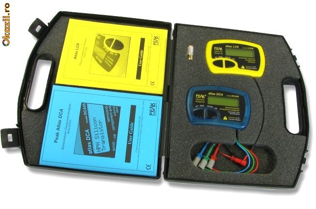
SET ANALIZOR INTELIGENT PT.SEMICONDUCTORI+ANALIZOR
INTELIGENT PENTRU COMPONENTE PASIVE
ANALIZOR INTELIGENT PENTRU
SEMICONDUCTORI
| Cu ajutorul acestui analizor inteligent pentru
semiconductoriputeti verifica
diode,led-uri,tranzistoare bipolare,cu efect de camp (FET si
MOSFET,triace si tiristori de mica putere.Este suficient sa
conectati terminalele testerului la semiconductor si el va spune
care sunt acestea fara sa mai rasfoiti vreun catalog.
The Peak Atlas DCA
A fresh approach to component analysis has resulted in the
fantastic Peak Atlas DCA, an intelligent, slim and invaluable tool.
A world of detailed component data has never been so
accessible.
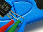
Just connect your
component any way round and press the test button. The Atlas
DCA will then present you with detailed component information in
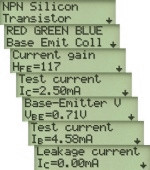
concise, easy to read, scrollable pages. The displayed information
will include: the component type, special component features,
component pinout, and measured parameters (such as gain, leakage
current, gate threshold voltages, volt drops etc...). No more
searching through data books and catalogues in order to identify
components and pinouts, the Atlas does it all.
|
Analysis Portfolio
It doesn't matter how you connect the test clips to the component,
the Atlas can analyse a vast number of different component types
including bipolar transistors, enhancement mode MOSFETs, depletion
mode MOSFETs, Junction FETs (only gate pin identified), low power
thyristors and triacs (less than 5mA trigger and hold), diodes,
multiple diode networks, LEDs, bi-colour and tri-colour LEDs. It
will even identify special component features such as diode
protection and shunt resistors in transistors. For two-leaded
components such as diodes and LEDs, any pair of test clips can be
applied to the component any way round, the Atlas DCA sorts it all
out for you.
Simplicity
There is no on/off switch, power is automatically turned on at the
start of an analysis and then automatically turned off if inactive
for more than 30 seconds. Each page of displayed information is
presented in manageable amounts, with each page being displayed
when you want it. If you want to concentrate on the "pinout" page
then just select that page, you don't have to see information that
you don't need.
| Parameters |
Minimum |
Typical |
Maximum |
Notes |
| Peak test current into S/C |
-5.5mA |
|
5.5mA |
1 |
| Peak test voltage across O/C |
-5.1V |
|
5.1V |
1 |
| Measurable transistor gain range (HFE) |
4 |
|
65,000 |
2 |
| Transistor gain accuracy |
-3%-5 HFE |
|
+3%+5 HFE |
2,9 |
| Transistor VCEO |
2.0V |
|
3.0V |
2 |
| Transistor VBEaccuracy |
-2%-20mV |
|
+2%+20mV |
9 |
| VBEthreshold for Darlington identification |
|
0.9V |
|
3 |
| VBEthreshold for Darlington identification (shunted) |
|
0.8V |
|
4 |
| Acceptable transistor VBE |
|
|
1.8V |
|
| Base-emitter shunt resistance threshold |
|
60k |
|
|
| Transistor collector-emitter test current |
2.45mA |
2.50mA |
2.55mA |
|
| Acceptable transistor collector leakage |
|
1.0mA |
|
6 |
| MOSFET gate threshold range |
0.1V |
|
5.0V |
5 |
| MOSFET gate threshold accuracy |
-2%-20mV |
|
+2%-20mV |
5 |
| MOSFET drain-source test current |
2.45mA |
2.50mA |
2.55mA |
|
| MOSFET minimum acceptable gate resistance |
|
8k |
|
|
| Thyristor/Triac gate test current |
|
4.5mA |
|
7 |
| Thyristor/Triac load test current |
|
5mA |
|
|
| Diode test current |
|
|
5mA |
|
| Diode forward voltage accuracy |
-2%-2mV |
|
+2%+2mV |
|
| VFthreshold for LED |
|
1.50V |
|
|
| Short circuit detection threshold |
|
10 ohms |
|
|
| Battery type |
GP23A 12V Alkaline |
| Battery voltage range |
7.50V |
12V |
|
|
| Battery voltage warning threshold |
|
8.25V |
|
|
| Inactivity power-down period |
|
30 secs |
|
|
| Dimensions (excluding test leads) |
103 x 70 x 20 mm |
| Operating temperature range |
0°C |
|
50°C |
8 |
|
|
Example screenshots for a typical
transistor: |
 |
| |
 |
- Between any pair of test clips.
- Collector current of 2.50mA.
- Resistance across reverse biased base-emitter > 60k.
- Resistance across reverse biased base-emitter < 60k.
- Drain-source current of 2.50mA.
- Collector-Emitter voltage of 5V.
- Thyristor quadrant 1, Triac quadrants I and III.
- Subject to acceptable LCD visibility.
- BJT with no shunt resistors.
The Atlas LCR is an advanced instrument that greatly simplifies the
testing of passive components. Traditional LCR bridges are
inherently complex and very time consuming to use. The Atlas LCR
does everything automatically, it tells you the component type in
addition to component value data. What’s more, the Atlas LCR
automatically selects the best signal level and frequency for the
particular component under test.
It doesn’t get any easier than this
Just clip the universal test leads to your component and press the
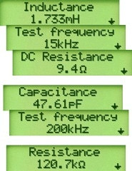
test button. In seconds, the Atlas LCR will identify the type of
component (Inductor, Capacitor or Resistor) together with the
component’s main value. Additionally, further component data is
also displayed, such as the DC resistance of an inductor. The test
frequency is automatically selected to suit the component under
test and this is also confirmed on the scrollable
display. |
|
|
|
| |
Flexible
The Atlas LCR is supplied with our new 2mm compatible detachable
micro-hooks, allowing the use of a range of 2mm compatible
probes. |
| Parameters |
Minimum |
Typical |
Maximum |
Notes |
| Resistance |
range |
1R |
|
2MR |
|
| resolution |
0.3R |
0.6R |
|
|
| accuracy |
Typically ±1.0% ±1.2R |
1,2,6 |
| Capacitance |
range |
0.5pF |
|
10,000µF |
|
| resolution |
0.2pF |
0.5pF |
|
|
| accuracy |
Typically ±1.5% ±1.0pF |
1,2,5 |
| Inductance |
range |
1µH |
|
10H |
|
| resolution |
0.4µH |
0.8µH |
|
|
| accuracy |
Typically ±1.5% ±1.6µH |
1,2,4 |
| Peak test voltage (across O/C) |
-1.05V |
|
+1.05V |
|
| Peak test current (thru S/C) |
-3.25mA |
|
+3.25mA |
|
Test
Frequency
Accuracy |
1kHz |
-1.5% |
±1% |
+1.5% |
|
| 14.925kHz |
-1.5% |
±1% |
+1.5% |
|
| 200kHz |
-1.5% |
±1% |
+1.5% |
|
| Sine Purity |
Typically -60dB 3rd harmonic |
|
| Operating temperature range |
10°C |
|
40°C |
3 |
| Battery operating Voltage |
8.5V |
|
13V |
|
|
|
Example screenshots for some typical
components: |
 |
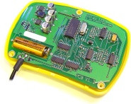
| A view inside: |
Notes for table above:
1. Within 12 months of factory calibration. Please contact us if
you require a full re-calibration and/or certification of traceable
calibration.
2. Specified at temperatures between 15°C and 30°C.
3. Subject to acceptable LCD visibility.
4. For inductances between 100µH and 100mH.
5. For capacitances between 200pF and 500nF.
6. For resistances between 10Ω and 1MΩ. |
 |
|
| |
| |
Va rog sa priviti si celelalte aparate pe care le am la
licitatie.
Pentru usurinta urmati link-ul: http://www.okazii.ro/catalog?user_list=honki55&sort=timp_ramas_desc
Va multumesc pentru atentia acordata.