 foto")
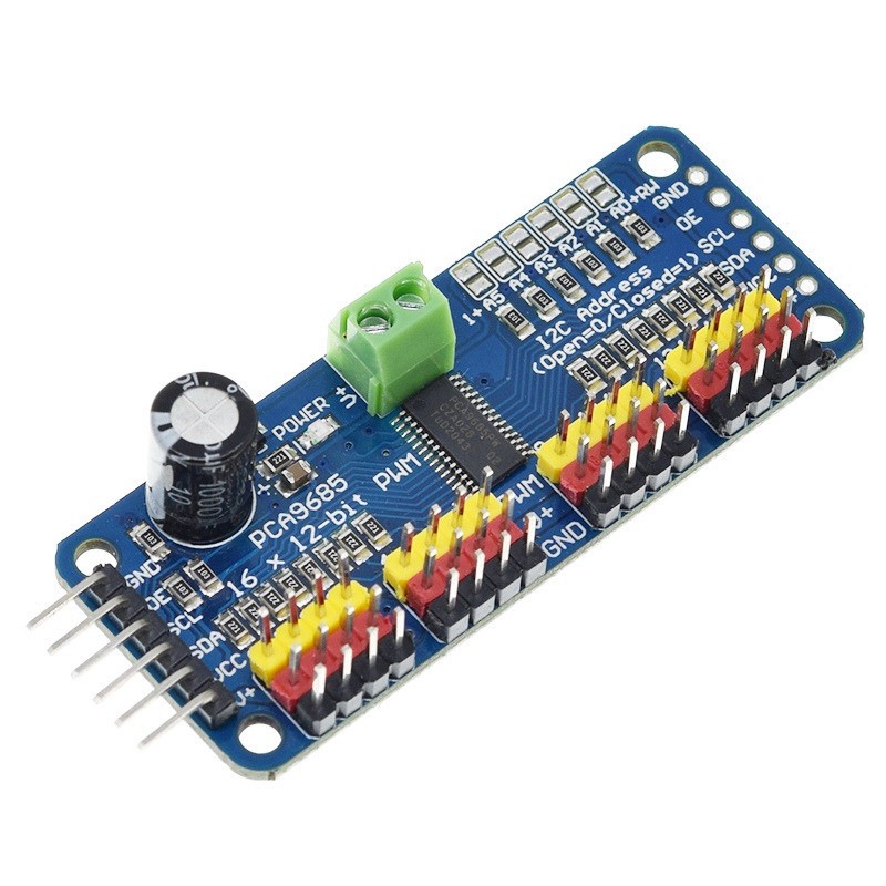
Driver servo motor PWM PCA9685 16 canale 12 biti Raspberry Pi, Arduino (p.1933W)
Livrare gratuita la comenzile de 180 lei
-
Produs:Nou, Fără garanție
-
Numar articol:218968479
-
Disponibilitate:Indisponibil
-
Preț:35,00 Lei
-
Anuntul a expirat la:11.09.2025, 10:31
-
Ai o nelamurire?
-
Vandut de:
-
Vinde si tu:Pune in vanzare un produs ca acesta
-
Optiuni:
Descriere
Vânzatorul este direct răspunzator pentru produsul afișat în această pagină.
Disponibilitate: Indisponibil - Vezi produse similare
Specificatii
Produsul este nou!
Produsul este la fel cu cel prezentat in fotografii!
Produsul este la fel cu cel prezentat in fotografii!
Specificații în limba
engleză:
Want to make a hexapod walker? Maybe you're making a
piece of art with tons of moving parts, or you need to drive a ton
of LEDs with precise PWM output.
Your microcontroller has a limited number of PWM
outputs, and you find yourself running out!
Not with the Adafruit 16-Channel 12-bit PWM/Servo Driver
- I2C interface.
With this pwm and servo driver breakout, you can control
16 free-running PWM outputs with just two pins!
Need to run more than 16 PWM outputs?
No problem.
Chain together up to 62 of these beauties for up to an
outstanding 992 PWM outputs.
Features:
Dimensions (no headers or terminal block) 62.5mm x
25.4mm x 3mm
Weight (no headers or terminal block):
5.5grams
Weight (with 3x4 headers & terminal block):
9grams
This board/chip uses I2C 7-bit address between
0x60-0x80, selectable with jumpers
Terminal block for power input (or you can use the 0.1"
breakouts on the side)
Reverse polarity protection on the terminal block
input
Green power-good LED
3 pin connectors in groups of 4 so you can plug in 16
servos at once (Servo plugs are slightly wider than 0.1" so you can
only stack 4 next to each other on 0.1" header
"Chain-able" design
A spot to place a big capacitor on the V+ line (in case
you need it)
220 ohm series resistors on all the output lines to
protect them, and to make driving LEDs trivial
Solder jumpers for the 6 address select
pins
i2c-controlled PWM driver with a built in clock. Unlike
the TLC5940 family, you do not need to continuously send it signal
tying up your microcontroller, its completely free
running!
It is 5V compliant, which means you can control it from
a 3.3V microcontroller and still safely drive up to 6V outputs
(this is good for when you want to control white or blue LEDs with
3.4+ forward voltages)
6 address select pins so you can wire up to 62 of these
on a single i2c bus, a total of 992 outputs - that's a lot of
servos or LEDs
Adjustable frequency PWM up to about 1.6
KHz
12-bit resolution for each output - for servos, that
means about 4us resolution at 60Hz update rate
Configurable push-pull or open-drain output
Output enable pin to quickly disable all the
outputs
(1)Drive board connected to Arduino:
The PWM driver board uses the I2C method, so only
four lines can be connected to the Arduino
device:
"Classic" Arduino pin mode:
+ 5v -> VCC
GND -> GND
Analog 4 -> SDA
Analog 5 -> SCL
Old Mega pin way:
+ 5v -> VCC
GND -> GND
Digital 20 -> SDA
Digital 21 -> SCL
R3 and later Arduino pin method (Uno, Mega
&
Leonardo):
(These boards have dedicated SDA and SCL
pins)
+ 5v -> VCC
GND -> GND
SDA -> SDA
SCL -> SCL
VCC pin is only for the chip power supply, if you
want to connect the servo or LED lights, use the V + pin power
supply, V + pin supports 3.3 ~ 6V power supply (chip safe voltage
5V). It is recommended to connect the external power supply via the
power supply terminal.
(2) power supply part:
Most of the servo design voltage is 5 ~ 6V,
especially in a number of steering gear at the same time running,
with the need for high-power power supply. If you are directly
using the Arduino 5V pin to power the servo directly, there are
some unpredictable problems, so we recommend that you have a
suitable external power supply for the drive
board.
(3) Connect the servo:
Most servos are connected using standard 3-wire
female plugs, as long as the corresponding pin into the driver
board on it. (Ground wire is generally black or brown, the signal
line is generally yellow or white)
(4) for the driver board assigned
address:
Each drive board of the cascade needs to have a
unique access address.
The initial I2C address of each driver board is 0
× 40, you can modify the upper right corner of the jumper I2C
address. Connect a jumper with solder to indicate a binary number
"1".
Atenție!
Se expediază în toată țara prin curierat rapid fără limită de kilometri în sistem ramburs.
Dacă aveți nelămuriri sau întrebări vă rog nu ezitați să sunați sau să-mi scrieți.
Modalitati de livrare si plata
LIVRARE
PLATA
- - Ramburs cu Garantia de Livrare

Curierul special îți livrează produsul pe care tu îl achiți la primire. Dacă produsul nu este ca în descriere, îți recuperezi banii, inclusiv taxele de transport.
Politica de retur
- - Produsul se poate returna in maxim 3 zile lucratoare
- - Metoda de retur: Ramburs contravaloare produs
- - Costul transportului va fi suportat de catre cumparator
- - Alte detalii: Retur acceptat in conditiile Garantiei de Livrare
Fii primul care scrie un review
Spune-ti parerea acordand o nota produsului
Nu ai gasit ce cautai?
Instaleaza aplicatia Okazii.ro