Produsul este nou!
Produsul este la
fel cu cel prezentat in
fotografii!
Specificații în limba
engleză:
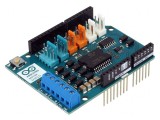
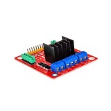
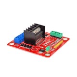
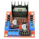
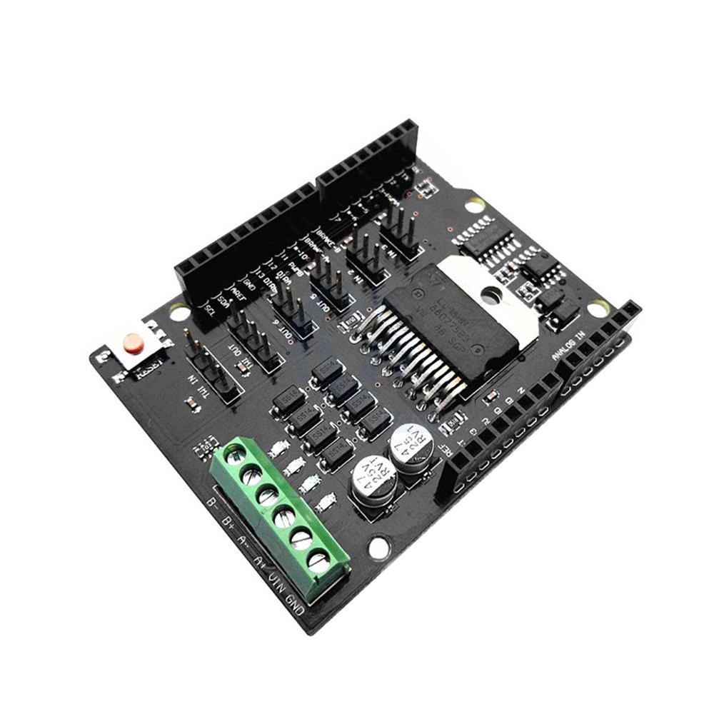
The Motor Shield is based on the L298NH, which is
a dual full-bridge driver designed to drive inductive loads such as
relays, solenoids, DC and stepping motors.
It lets you drive two DC motors with your for
Arduino board, controlling the speed and direction of each one
independently.
You can also measure the motor current absorption
of each motor, among other features.
•You can find in the Getting Started section all
the information you need to configure your board, use the for
Arduino Software (IDE), and start tinker with coding and
electronics.
Technical
specs
Operating
Voltage 5V
to 12V
Motor
controller L298HN,
Drives 2 DC motors or 1 stepper motor
Max
current 2A
per channel or 4A max (with external power
supply)
Current
sensing 1.65V/A
Free running stop and brake
function
Power
The Motor Shield must be powered only by an
external power supply. Because the L298HN IC mounted on the shield
has two separate power connections, one for the logic and one for
the motor supply driver. The required motor current often exceeds
the maximum USB current rating.
External (non-USB) power can come either from an
AC-to-DC adapter (wall-wart) or battery. The adapter can be
connected by plugging a 2.1mm center-positive plug into the for
Arduino board power jack on which the motor shield is mounted
or by connecting the wires that lead the power supply to the Vin
and GND screw terminals, taking care to respect the
polarities.
To avoid possible damage to the for Arduino board
on which the shield is mounted, we reccomend using an external
power supply that provides a voltage between 7 and
12V.
If your motor require more than 9V we recommend
that you separate the power lines of the shield and the for Arduino
board on which the shield is mounted.
This is possible by cutting the "Vin Connect"
jumper placed on the back side of the shield. The absolute limit
for the Vin at the screw terminals is 18V.
The shield can supply 2 amperes per channel, for a
total of 4 amperes maximum.
Input and
Output
This shield has two separate channels, called A
and B, that each use 4 of the for Arduino pins to drive or sense
the motor.
In total there are 8 pins in use on this shield.
You can use each channel separately to drive two DC motors or
combine them to drive one bipolar stepper
motor.
The shield's pins, divided by channel are shown in
the table below:
Function pins
per Ch.
A pins
per Ch. B
Direction D12
D13
PWM
D3 D11
Brake
D9 D8
Current
Sensing A0 A1
If you don't need the Brake and the Current
Sensing and you also need more pins for your application you can
disable this features by cutting the respective jumpers on the back
side of the shield.
Motors
Connection
Brushed DC motor.
You can drive two Brushed DC motors by connecting
the two wires of each one in the (+) and (-) screw terminals for
each channel A and B.
In this way you can control its direction by
setting HIGH or LOW the DIR A and DIR B pins, you can control the
speed by varying the PWM A and PWM B duty cycle
values.
The Brake A and Brake B pins, if set HIGH, will
effectively brake the DC motors rather than let them slow down by
cutting the power.
You can measure the current going through the DC
motor by reading the SNS0 and SNS1 pins.
On each channel will be a voltage proportional to
the measured current, which can be read as a normal analog input,
through the function analogRead() on the analog input A0 and
A1.
For your convenience it is calibrated to be 3.3V
when the channel is delivering its maximum possible current, that
is 2A.
Pachetul conține:
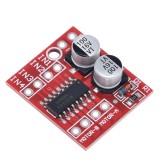
• 1 bucată x L298NH dual channel DC motor driver shield board
replace L298P (cod produs: a.3307E)
Se expediază în toată țara prin curierat rapid în
sistem ramburs.
 foto")


")